PROCEDURAL GENERATION SYSTEM
Project Type : University/ Solo Project
Software Used : Unity, JetBrainRider
Languages Used : C#
Context
P.T.W.D is a project I developed during my second year, and it marked a significant milestone in my programming journey. It was through this project that I was introduced to foundational programming concepts, especially Object-Oriented Programming (OOP) and design patterns. Working on it helped me strengthen my skills in writing efficient and well-structured code while gaining a deeper appreciation for best practices.
Procedural Generation System Structure
Data Structures
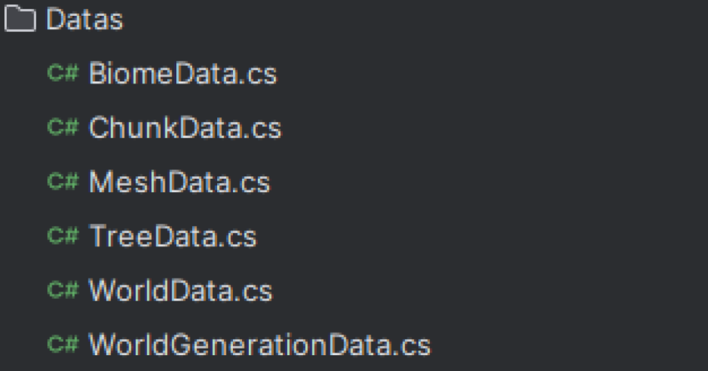
The data structures in the project serve as the foundation for managing terrain meshes within the system. They are designed to efficiently organize and store essential information, ensuring the system operates smoothly. Separating the different structures allowed me to adheres to the Single Responsibility Principle (SRP) resulting in a modular, maintainable, and scalable architecture.

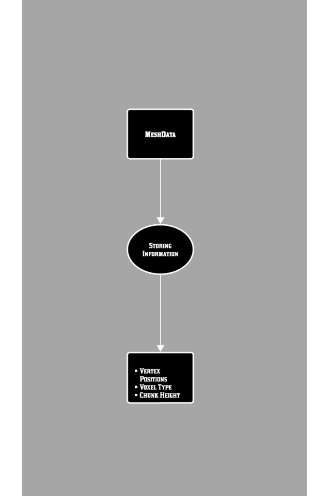
UML diagram of the Mesh Data Structure
This UML diagram represents the basic structure of the Mesh Data, it was a part of my design process.
CODE SNIPPET - MeshData Script
The following code demonstrates the structure of the MeshData.

Renderers
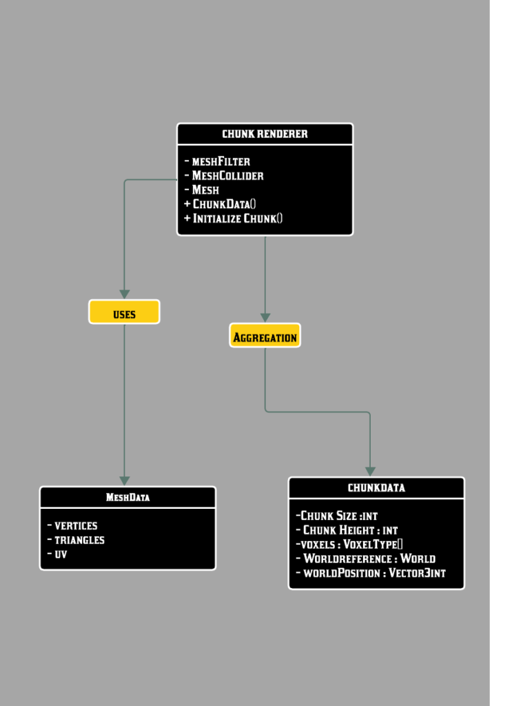
The renderers in the project play a crucial role in bringing the world to life by turning data into visible elements. They work by taking structured data, such as mesh information and chunk details, and transforming it into something that can be displayed on the screen.

UML diagram example relationShips Data Structures and the Chunk Renderer
This UML diagram represents the relationship between the Renderer and the MeshData and ChunkData structures .
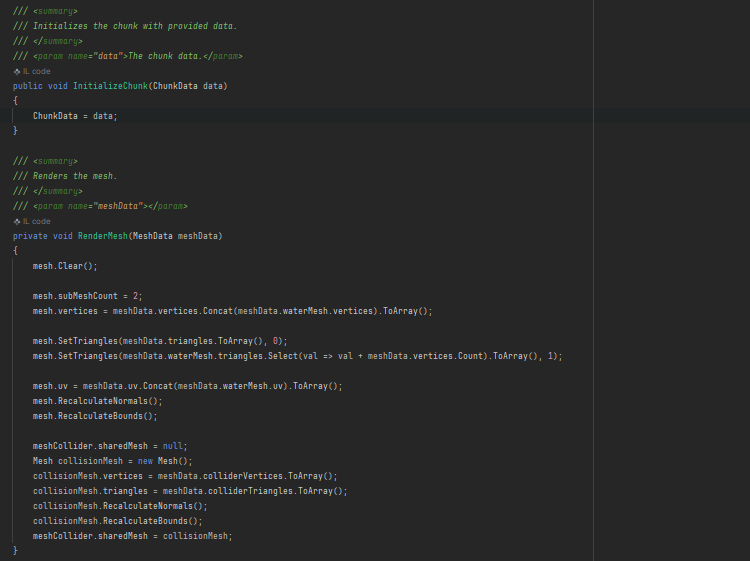
CODE SNIPPET - Renderer
The following code demonstrates how the renderer uses the data structures.
Generators
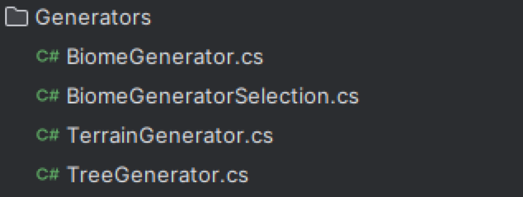
The Generators are here in order to create diverse terrains. Each generator focuses on a specific aspect of the terrain generation , ensuring modularity and adherence to the SRP principle. They allow to produce biomes, terrains and trees dynamically.
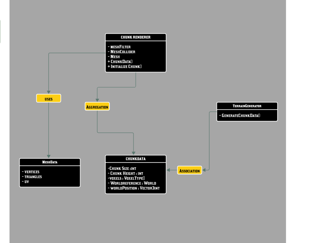
UML diagram relationShip Data Structures and Renderer and Generator
This UML Diagram represents the relationship between the ChunkData and TerrainGenerator.
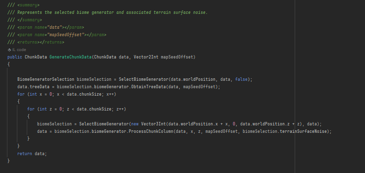
CODE SNIPPET - Terrain Generator Method interacting with ChunkData
This part of the TerrainGenerator Script represents how the Chunk data is used in order to generate the terrain.
Design Patterns and Techniques used to improve the System
Optimization with Multi Threading and Coroutines
Why did I implement these techniques?
During the development of the system, I encountered issues with performance. The FPS were low, and the game lagged whenever the player moved to a new edge of the terrain, requiring the system to process chunk generation. After conducting research, I discovered that the root cause was that all the chunk generation processes were being executed on the main thread. This created a bottleneck, as the main thread was overwhelmed.
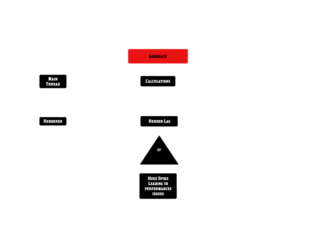
The way to solve this issue
The solution to this issue was to implement multi-threading for the intensive computations and coroutines for the rendering. By doing so, I enabled real-time terrain generation and rendering without impacting gameplay performance.
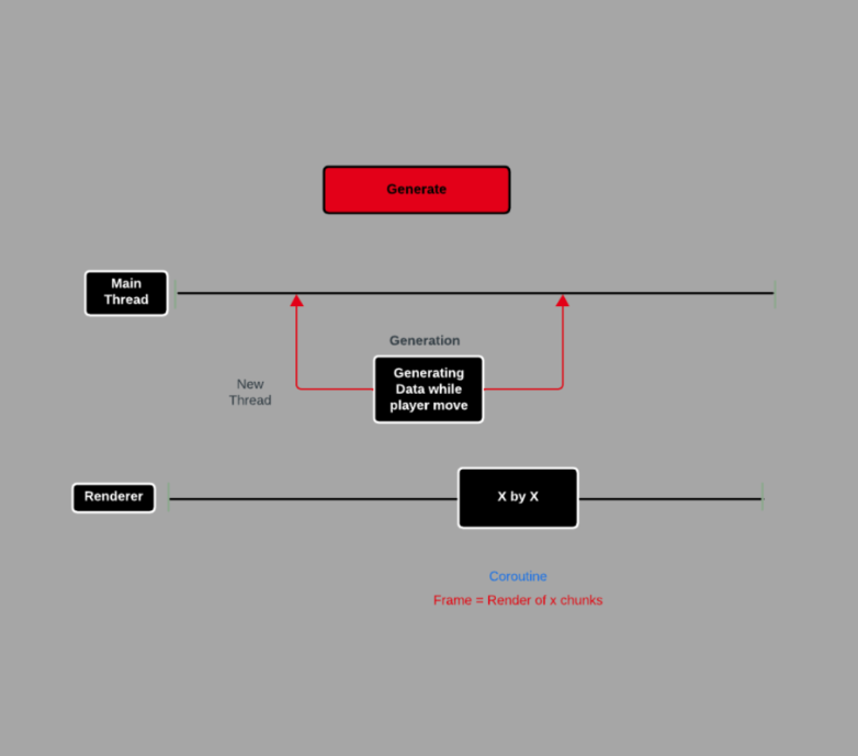
Flow chart of the Coroutine and the Threading
This flowchart illustrates how multithreading and coroutines collaborate within the system. It provides a clear overview of the process flow, helping me better understand how they work together effectively.
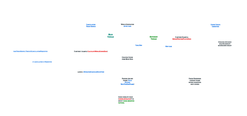
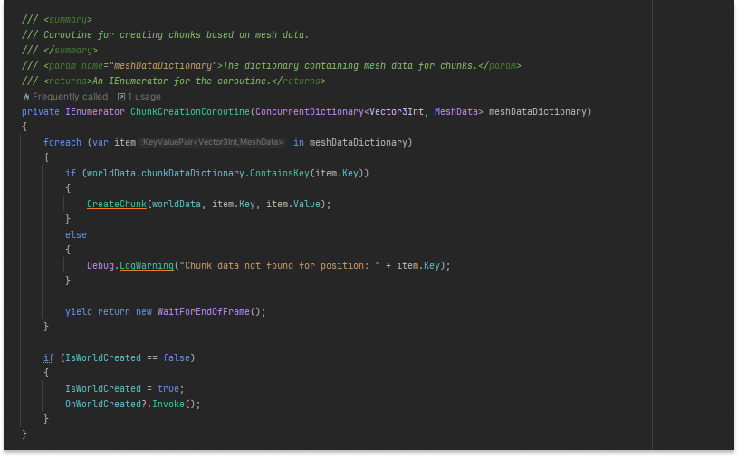
CODE SNIPPET - Coroutine and Threading
These methods are parts of the coroutine and threading process
Coroutine
Task

Object Pooling
Why did I implement this design pattern?
To improve the system’s performance, I implemented the Object Pooling design pattern. Initially, all chunks in the world were rendered simultaneously during gameplay, which led to significant performance issues. By adopting this pattern, I optimized chunk rendering by activating and displaying only the chunks near the player, while disabling and returning distant chunks to a reusable pool. This approach significantly reduced memory and CPU usage, resulting in smoother gameplay and enhanced overall performance.
Flow chart Explaining the Design Pattern
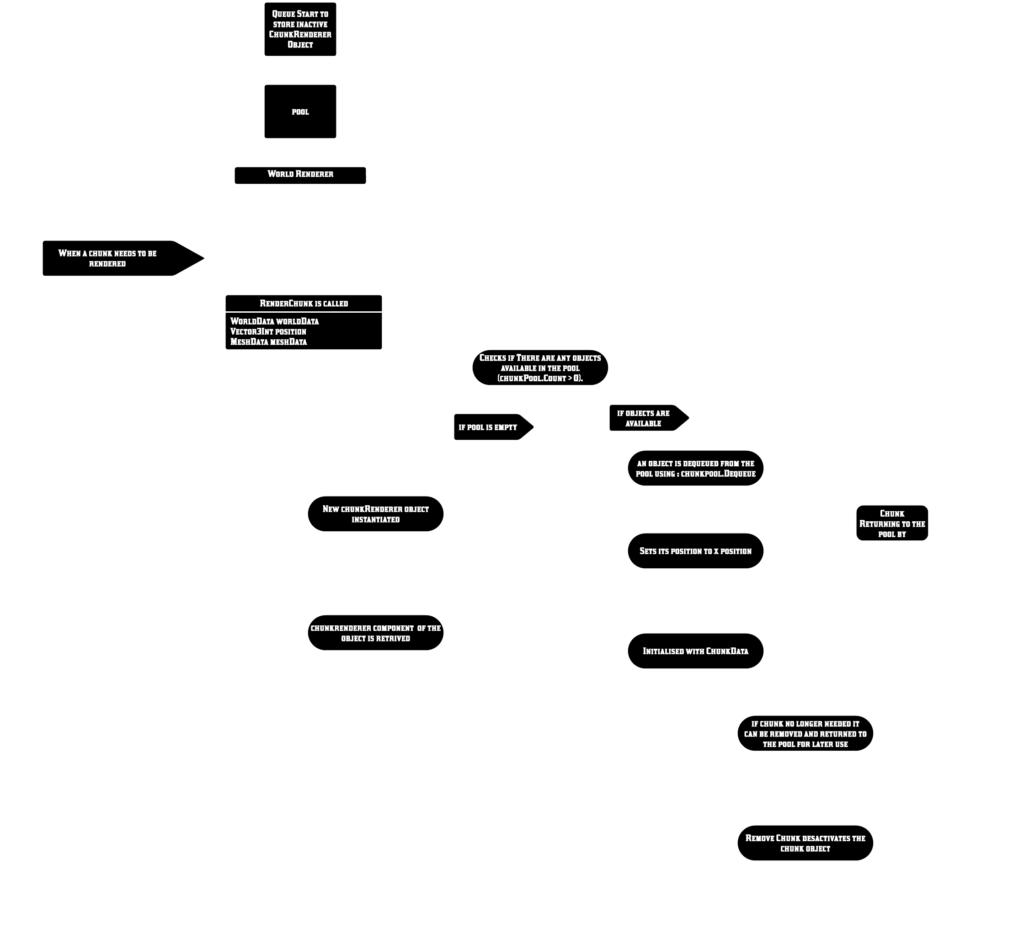
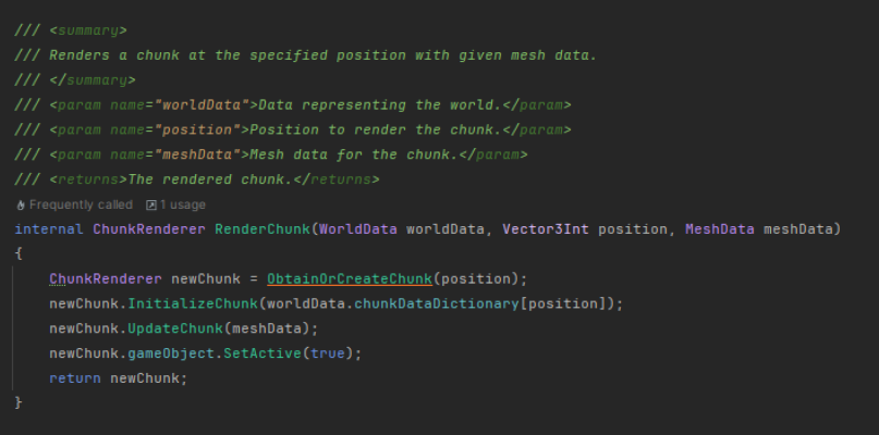
CODE SNIPPET - taKey points of the WorldRenderer Script implementing Object Pooling
The following code demonstrates the structure of the worldrenderer which helps the world class in order to use the object pooling.


Chain of Responsabilities
Why did I implement this design pattern?
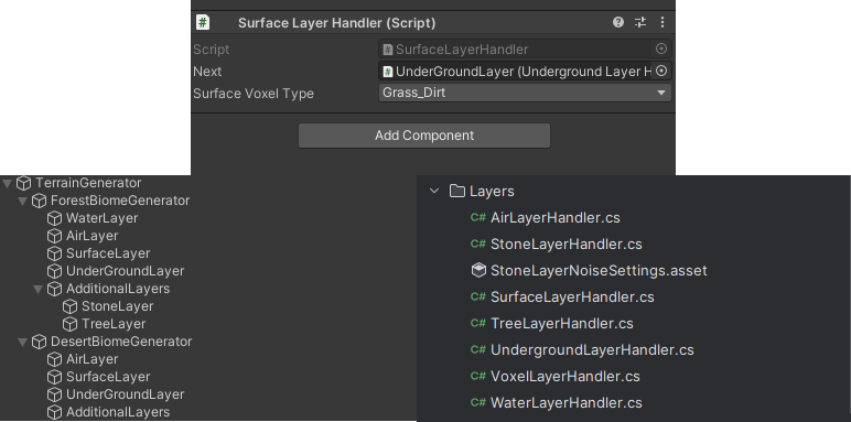
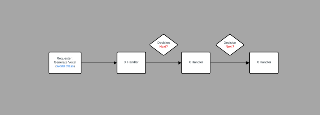
I implemented the Chain of Responsibility design pattern to make voxel generation for procedural terrain more efficient and organized. This pattern sets up a pipeline of handlers, where each one is responsible for generating a specific voxel layer, like the surface, underground, or bedrock. If a handler can’t process a particular voxel, it passes the task to the next one in the chain. This approach made my code more reusable, easier to scale, and better aligned with the Single Responsibility Principle by keeping each handler focused on its specific task.
Flow chart Explaining the Design Pattern
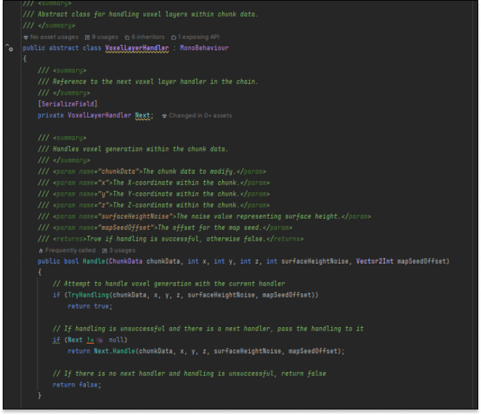
CODE SNIPPET Layers using an abstract class
The following script shows how the layers work :
Add Your Heading Text Here
Lorem ipsum dolor sit amet, consectetur adipiscing elit. Ut elit tellus, luctus nec ullamcorper mattis, pulvinar dapibus leo.
